
Axial
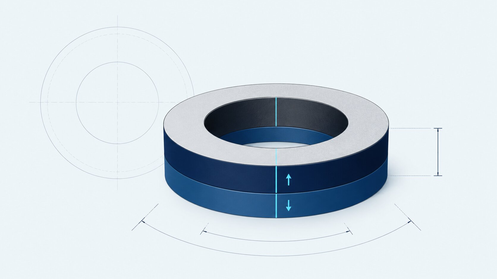
North and south are positioned on the two opposing flat faces. This is one of the most common ring magnet configurations.
Drawing focusIdentify which flat face should be north and whether it requires a polarity mark.


Date
19 August 2026
Category
Author
Conal McLaughlin
Ring magnets can appear straightforward: a circular magnet with a hole through its centre. In practice, two rings with the same outer dimensions can produce very different magnetic fields depending on their inner diameter, thickness, material, grade, magnetisation direction and pole arrangement.
GUK Magnetics receives requirements ranging from small sensor rings measuring only a few millimetres to thin 90 mm diameter rings and multipole rings for motor applications. These enquiries demonstrate why “ring magnet” is not a complete specification.
To assess manufacturability, price and expected performance, the requirement should define the outer diameter, inner diameter, thickness, tolerances, material, coating and complete magnetisation pattern.
Key takeaway: OD, ID and thickness define the ring’s geometry. Magnetisation direction and polarity define where its usable magnetic field appears.
A requirement written as 20 mm OD × 12 mm ID × 2 mm T describes a 20 mm outside diameter, 12 mm bore and 2 mm distance between the flat faces.
Controls the overall envelope and how the magnet fits within a housing, sleeve, rotor or surrounding assembly.
Defines the bore for a shaft, fastener, sleeve, sensor or central passage. Clearance and concentricity may be critical.
The distance between the flat faces. For an axially magnetised ring, this is also the magnetisation length.
The magnetic material between the bore and outside diameter. Very thin walls can restrict manufacturability and handling strength.
The outer diameter normally determines how the ring fits within a housing, rotor, sleeve or other surrounding component. It should be specified as a finished dimension with an appropriate tolerance.
If the ring is fitted inside another component, the drawing should define the intended clearance or interference. Allowance may also be required for the magnet coating, adhesive, a protective sleeve and variation within the mating component.
A larger OD generally provides more magnetic material, but it does not automatically produce a proportionate increase in useful field or force. The result also depends on the ID, thickness, grade, air gap and surrounding magnetic circuit.
The inner diameter may accommodate a shaft, fastener, bearing, sleeve, fluid passage, optical path or sensor. It is important to distinguish the actual magnet bore from the clearance required by the final assembly.
A ring should not automatically be specified with the same ID as the shaft it surrounds. The assembly may require allowance for adhesive, coating thickness, thermal movement, shaft runout or a separate protective sleeve.
For rotating components, concentricity between the ID and OD can be more important than the individual diameter tolerances. A ring that meets both size limits but has an off-centre bore may still create unacceptable runout or an uneven working air gap.
Thickness is the distance between the two flat faces of the ring. It may also be described as height where the component is shown standing vertically.
For an axially magnetised ring, thickness is the magnetisation length. Increasing it changes the magnet’s aspect ratio and can improve the field at some working distances, but the benefit is not necessarily linear. Once the magnetic circuit or surrounding steel approaches saturation, additional material may produce progressively smaller gains.
The selection should therefore be based on the required performance at the real air gap—not magnet volume alone.
A drawing should identify which dimensions are genuinely critical. Applying unnecessarily tight tolerances to the OD, ID and thickness can increase grinding and inspection costs without improving the finished assembly.
Depending on the application, the relevant controls may include:
Magnets are hard but brittle. Thin walls, sharp edges and large diameter-to-thickness ratios can increase the risk of chipping or fracture during manufacture, coating, transport and assembly. Small chamfers or edge radii may be preferable to perfectly sharp edges, provided they do not interfere with the magnetic circuit.
Magnetisation direction describes the direction in which the magnetic field is established within the magnet. Polarity describes where its north and south poles are located.
A drawing stating only “north pole required” is incomplete. It should show both the magnetisation direction and the required position of the north pole.
North and south are positioned on the two opposing flat faces. This is one of the most common ring magnet configurations.
North and south sit on opposing sides of the circumference. The field changes as the ring rotates past a fixed sensor.
One curved surface has one polarity and the opposing curved surface has the other. The direction may face inward or outward.
Several alternating north and south poles are arranged around a flat face, the ID or the OD.
In an axially magnetised ring, the field runs through the thickness. One flat face is north and the opposite face is south. Drawings may describe this as “axially magnetised”, “magnetised through thickness” or “north on marked face”.
Words such as “top” and “bottom” should only be used where the drawing clearly defines the component’s orientation. Referencing a datum or marked face removes this ambiguity.
A diametrically magnetised ring has north and south regions on opposing sides of its circumference. This can be useful where rotation of the ring needs to create a changing magnetic field at a fixed sensor.
If the pole axis must align with another component, the drawing should define its angular position relative to a physical datum.
In a true radially magnetised ring, the inner and outer curved surfaces have opposing polarities. This is different from diametric magnetisation, where two main pole regions sit on opposite sides of the circumference.
A one-piece radially oriented ring can require a specialist production route and magnetising fixture. For anisotropic sintered magnets, the required material orientation may need to be established during manufacture rather than applied to a conventional ring afterwards.
The magnetic axis crosses the complete ring from one side to the opposite side.
The magnetic direction follows the local radius between the inner and outer surfaces.
A multipole ring contains several alternating north and south poles around a specified surface. The pattern may be axial, with poles on a flat face, or arranged around the inner or outer circumference.
The specification should define the total pole count, pole pitch, working surface, north-south sequence and angular position relative to a datum. Specialist patterns normally require a purpose-built magnetising fixture, which can affect tooling cost, minimum quantities and lead time.
For a fuller explanation of these patterns, see Magnetisation Directions: Axial, Diametric, Radial & Multipole.
Magnetisation direction establishes the axis or pole pattern. The drawing must then identify which face or surface should be north.
Where operators need to identify polarity during assembly, specify the marking method. This may be an ink mark, dot, engraved feature or inspection requirement, subject to the coating and application.
Changing the OD, ID or thickness alters the quantity and distribution of magnetic material. No individual dimension determines performance on its own.
A higher material grade is therefore not always the most efficient answer. An N52 ring can have a higher remanence than an N35 ring, but useful field and force still depend on geometry, air gap and the complete magnetic circuit.
Where performance is critical, state what must be achieved and where it should be measured. This could be flux density at a specified distance, pull force against a defined steel target, magnet-to-magnet force at a stated air gap, sensor activation distance, torque or field uniformity through the bore.
Our guide to magnet strength, pull force, gauss, Br and BHmax explains why these terms should not be used interchangeably.
High magnetic performance in a compact volume. Frequently used in sensors, motors, couplings and holding assemblies. A suitable protective coating is normally required.
Compact size · high magnetic outputOften considered where temperature stability and resistance to demagnetisation are more important than achieving maximum output from the smallest volume.
Temperature stability · high coercivityCost-effective and naturally corrosion-resistant. Its lower magnetic performance may require a larger ring than an equivalent rare-earth design.
Cost-effective · corrosion resistantCan provide greater geometric and pole-pattern flexibility, including moulded multipole rings, although output is normally lower than comparable sintered rare-earth material.
Flexible pole patterns · moulded geometryThe grade should be selected against the required working temperature, magnetic circuit and demagnetisation conditions—not simply by choosing the highest available grade.
Not every magnet with a central hole should be treated as a simple ring. Custom features can include countersinks, stepped bores, tapered holes, radial slots, keyways, partial rings and arc segments.
Countersunk magnets require particular care because the countersink removes magnetic material and creates a thinner, more fragile region around the hole. The drawing should define the countersink diameter, through-hole diameter, included angle, depth, magnetisation direction and required pole on the countersunk face.
Permanent magnets should not be treated like conventional metal components that can simply be drilled or modified during assembly. Machining can damage the magnet, compromise the protective coating and create a significant risk of fracture.
A one-piece ring can simplify assembly and mechanical balance, but it is not always the most practical manufacturing route. Large diameters, thin walls, radial orientation and complex multipole requirements can make a segmented construction more suitable.
Potential routes include a one-piece sintered ring, a bonded or injection-moulded ring, or an assembly of individually magnetised arc segments. The appropriate option depends on the required output, dimensions, temperature, pole pattern, quantity and acceptable tooling cost.
Provide as much of the following information as is available. A drawing is strongly recommended where tolerances, alignment, countersinks or multipole magnetisation are involved.
The following example demonstrates the level of information that makes a ring magnet enquiry easier to assess. It is illustrative rather than a recommended design.
20 mm OD × 12 mm ID × 2 mm thickness. OD, ID and thickness tolerances as shown on drawing. Axially magnetised through the 2 mm thickness, with north pole on the marked face. NiCuNi coating, with dimensions applying to the finished coated component. Maximum continuous operating temperature 100°C. Initial quantity 3,000 pieces, with anticipated repeat supply.
This provides considerably more information than requesting a “20 mm ring magnet” and allows the manufacturing route, price and lead time to be considered properly.
GUK Magnetics supplies custom ring magnets in neodymium, samarium cobalt, ferrite and other permanent magnet materials, subject to the required geometry and application.
Our role is to review the magnet requirement, advise on manufacturability and identify suitable material, grade, coating, magnetisation or assembly options. Final application performance should be validated within the intended product or magnetic circuit.
Send your drawing, OD, ID, thickness, pole arrangement, operating conditions and anticipated quantities. We can review manufacturability and advise on practical magnet or assembly supply options.
Discuss Your RequirementsA ring magnet is normally specified as outer diameter × inner diameter × thickness. For example, 20 mm OD × 12 mm ID × 2 mm thick.
Usually. Both describe the distance between the two flat faces. Because drawing orientation can vary, label the relevant dimension clearly rather than relying on terminology alone.
An axially magnetised ring has its main poles on the two flat faces. A true radially magnetised ring has opposing polarity on its inner and outer curved surfaces.
No. Diametric magnetisation crosses the ring from one side to the opposite side. Radial magnetisation follows the local radius between the ID and OD.
Yes. Multipole rings can have alternating poles on a flat face or around the ID or OD. The pole count, pitch, working surface and alignment should be defined on the drawing.
Reducing the ID adds magnetic material and increases wall thickness, but the effect on useful field or force depends on the complete geometry, air gap and magnetic circuit. The increase should not be assumed to be proportional.
Yes, subject to material, dimensions and manufacturability. A countersink reduces the available magnetic material and can make the magnet more vulnerable to chipping, so the complete hole geometry should be shown on a drawing.
A drawing is strongly recommended for custom rings, particularly where tolerances, pole alignment, countersinks or multipole magnetisation are involved. For an initial review, a complete written specification may be sufficient for simpler requirements.
Crafted By Rapid