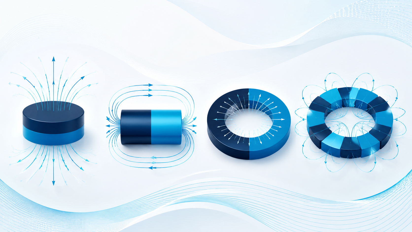
Magnetisation direction determines where a magnet’s poles appear and how its field interacts with an application. This guide explains axial, diametric, radial and multipole patterns.
Magnetisation direction defines where the north and south poles appear on a permanent magnet. It determines how the magnetic field leaves the component, which surface becomes the working face and how the magnet interacts with a sensor, steel target, rotor, coupling or adjoining magnet.
Two magnets made from the same material, grade and dimensions can behave very differently if they are magnetised in different directions. A disc magnetised through its thickness concentrates its usable field on the two flat faces. The same disc magnetised across its diameter places the poles on opposite sides of its curved surface.
For this reason, magnetisation direction should be treated as part of the magnet specification—not as a detail to decide after the geometry has been fixed.
Key takeaway: Magnetisation direction determines where the usable field appears. Material, grade and dimensions alone do not fully define how a magnet will perform within an application.
At a glance
The four main magnetisation patterns
These simplified diagrams show the usual pole positions. North and south may be reversed, so the required polarity and working surface should always be confirmed on the component drawing.
Axial
Along the main axis or through the thickness
The poles appear on the two opposing flat or end faces, creating a clear working pole face.
PolesOpposing flat or end faces
ShapesDiscs, cylinders, rings and blocks
UsesHolding, sensing and face-to-face coupling
Drawing focus: identify the axis or thickness and specify which datum face should be north.
Diametric
Across the full diameter
The two main pole regions sit on opposite sides of the curved surface rather than on the end faces.
PolesOpposite sides of the circumference
ShapesCylinders and rings
UsesRotary sensing, switching and selected couplings
Drawing focus: define the pole centreline relative to an angular datum or physical feature.
Radial
Along each local radius
The field runs between the inner and outer curved surfaces. The inward or outward polarity can be reversed.
PolesInner and outer curved surfaces
ShapesRings and arc segments
UsesMotors, generators and cylindrical couplings
Drawing focus: state whether north is required on the inside or outside diameter.
Multipole
Several alternating pole regions
Alternating north and south poles are arranged on a face, around a circumference or along a strip.
PolesSeveral alternating N-S regions
ShapesRings, discs, strips and moulded parts
UsesEncoders, motors and position sensors
Drawing focus: define pole count, pitch, working surface and starting-pole position.
What does magnetisation direction mean?
A permanent magnet develops a preferred magnetic axis when it is magnetised. The direction of this axis relative to the part geometry determines the position of the poles and the shape of the external field.
The term can become ambiguous when words such as length, height and thickness are used without a drawing. On a cylindrical magnet, axial usually means along the centreline. On a thin disc or block, the same direction may be described as through-thickness. A drawing with a direction arrow and an identified pole face is much clearer than terminology alone.
Material orientation is related, but not identical
Magnetic orientation is established during manufacture for anisotropic materials. The particles or grains are aligned along a preferred—or easy—axis before the part receives its final magnetising pulse. To achieve the expected material properties, the finished magnet normally needs to be magnetised along this orientation direction.
Isotropic materials do not have the same strongly preferred direction and can offer greater freedom in the final pole pattern, although their magnetic output is normally lower than that of an equivalent anisotropic material. This distinction is important when considering unusual radial or multipole patterns.
Axial magnetisation
Axial magnetisation runs along the main axis of a magnet. On a disc, cylinder or ring, the north and south poles are positioned on the two opposing flat faces. For a block, it is often described as magnetisation through the thickness, although the relevant dimension should still be identified on the drawing.
This is one of the most common permanent-magnet configurations because it produces a clear working pole face and can be straightforward to manufacture and inspect.
Where axial magnetisation is commonly used
Holding or attachment applications where a flat pole face acts against steel
Reed switches and Hall-effect sensing where the sensor approaches an end face
Face-to-face magnetic couplings
Stacked magnet assemblies
Disc or ring magnets fitted into a housing with one exposed working face
Example drawing note: Axially magnetised through the 5 mm thickness. North pole on datum face A.
Diametric magnetisation
A diametrically magnetised cylinder or ring has its magnetic axis across the diameter. One side of the curved surface behaves as the north-pole region while the opposite side behaves as the south-pole region. The end faces are not the main opposing pole faces.
This arrangement is useful when the field needs to change as the magnet rotates. A sensor positioned beside a diametrically magnetised cylinder can detect north and south during each revolution, making the configuration suitable for certain position, speed or switching functions.
Where diametric magnetisation is commonly used
Rotary position sensing
Speed sensing and switching
Small cylindrical rotors
Magnetic couplings where the field is required across the diameter
Applications in which the curved side is the working surface
Example drawing note: Diametrically magnetised across the outside diameter. North-pole centreline aligned with angular datum B.
Radial magnetisation
Radial magnetisation follows the radius of a ring or curved segment. In a simple radially magnetised ring, one cylindrical surface can form one pole and the opposing inner or outer surface forms the other. The polarity can face inward or outward depending on the requirement.
For an arc segment, the magnetic axis follows the local radius between the inner and outer curved surfaces. Several radially magnetised arc segments can therefore be arranged around a rotor or stator to create an alternating pole pattern.
A one-piece radially oriented ring is more specialised than a conventional axially or diametrically magnetised component. Feasibility depends on material, grade, dimensions, wall thickness, production route, pole requirement and expected quantity. Dedicated orientation or magnetising tooling may be required.
Where radial magnetisation is commonly used
Electric motors and generators
Magnetic couplings
Rotor and stator assemblies
Speaker and actuator magnetic circuits
Applications requiring an inner- or outer-diameter working surface
Example drawing note: Radially magnetised through the ring wall, with north pole on the outside diameter and south pole on the inside diameter.
Radial and diametric magnetisation are not the same
The terms are sometimes used interchangeably, particularly for ring magnets, but they describe different field directions.
Across the full diameter
NS
Diametric magnetisation
The magnetic axis crosses the ring or cylinder from one side to the opposite side.
Practical resultTwo main pole regions appear on opposite sides of the circumference.
Along each local radius
IDOD
Radial magnetisation
The magnetic axis follows the local radius between the inner and outer surfaces.
Practical resultThe inside and outside surfaces, or radially arranged sectors, become the working pole regions.
If the distinction matters to the application, include a sectional drawing or pole diagram. A written description alone can be misinterpreted.
Multipole magnetisation
Multipole magnetisation creates several alternating north and south poles on a specified surface. The poles may be distributed around a circumference, across a flat face or along the length of a strip. Multipole is therefore a pole pattern rather than one single geometric direction.
Examples include an axially multipole ring with alternating poles on one flat face, or a ring with alternating poles arranged around its outside diameter. The number of poles, pole pitch, working surface and angular position all influence the resulting magnetic waveform.
Multipole patterns normally require a purpose-built magnetising fixture. As the number of poles increases, the available pole pitch becomes smaller and the material, geometry and measuring distance become increasingly important. The achievable surface field and waveform should be reviewed against the real sensor or motor requirement rather than specified as pole count alone.
Where multipole magnetisation is commonly used
Rotary encoders
Brushless motors and compact rotors
Speed and position sensors
Magnetic rings used with Hall or magnetoresistive sensing
Linear magnetic strips and indexing applications
Example drawing note: Eight poles, alternating N-S around the outside diameter. Equal 45-degree pole pitch. Pole transition and starting-pole position referenced to datum feature C.
How magnetisation direction affects application performance
Magnetisation direction does not change the basic alloy grade, but it changes where the field is available and how effectively the magnet works within the magnetic circuit.
Working face: The pole face selected by the magnetisation direction determines where the strongest usable external field normally appears.
Pull force: A pull-force estimate assumes a particular pole face, contact condition and steel target. Turning an axially magnetised disc onto its curved side will not reproduce the stated face pull.
Sensor output: Pole position, working distance and angular alignment affect the amplitude and waveform detected by a sensor.
Torque and coupling: Pole count, pole pitch, air gap and relative alignment influence the torque available from a motor or magnetic coupling.
Assembly behaviour: Adjacent magnets may attract, repel or experience demagnetising fields depending on their orientation in the assembly.
For an initial estimate of face pull, use the GUK Magnetic Pull Force Calculator. Results assume idealised conditions and should not be treated as a substitute for testing in the final configuration.
How material and manufacturing route affect feasibility
NdFeB / SmCoSintered rare-earth magnets
High magnetic performance and normally anisotropic. Conventional axial or diametric directions are common; specialised radial or multipole patterns may require dedicated tooling, a different production route or a segmented assembly.
High output · orientation-sensitiveFerriteSintered ferrite magnets
Available in isotropic and anisotropic forms. Rings and arc segments are widely used, but achievable direction and output depend on how the material was oriented during pressing.
Isotropic and anisotropic optionsBondedBonded or injection-moulded magnets
Can offer greater geometric and pole-pattern flexibility, including multipole rings. Magnetic output is normally lower than comparable sintered rare-earth material.
Direction, geometry and magnetic-circuit conditions require care because AlNiCo has relatively low coercivity. The intended operating point and risk of demagnetisation should be considered.
Magnetic circuit requires particular care
These are general manufacturing considerations, not universal capability limits. Final feasibility depends on the complete specification and supplier process.
How to specify magnetisation on a drawing or RFQ
The most useful magnetisation specification links the pole direction to the geometry and intended working surface. Where possible, include a drawing with a clear direction arrow, pole labels and a physical datum.
Information to includeProvide as much of the following as is available for an initial review.
Magnet shape and complete dimensions
Material family and grade, if known
Magnetisation direction shown by an arrow
Required north- and south-pole positions
Working face, inside diameter, outside diameter or sensor-facing surface
Number of poles and pole pitch for a multipole component
Angular position relative to a key, flat, hole or datum
Required field, flux density or sensor signal and measuring distance
Operating temperature, air gap and any opposing magnetic field
Whether the magnet will be supplied loose or within an assembly
Whether delivery is required magnetised or unmagnetised
The correct magnetisation direction is not automatically the pattern that produces the highest field at one surface. It is the pattern that places the required field in the correct location while remaining practical to manufacture, assemble and inspect.
Flat holding face against steel→Axial or through-thickness magnetisation is often the starting point.
One north-south cycle per revolution→A diametrically magnetised cylinder or ring may be appropriate.
Several position changes per revolution→A multipole ring may provide the required pole transitions.
Motor rotor or cylindrical coupling→Radial, multipole or segmented arc arrangements may be considered, depending on the magnetic circuit.
Uncertain application requirement→Provide the geometry, working face, field target, air gap and operating conditions for technical review.
Can an existing magnet be remagnetised in a different direction?
A magnet can sometimes be demagnetised and magnetised again, but changing the axis is not simply a matter of applying a new field. For anisotropic magnets, the preferred orientation was established during manufacture. Remagnetising across a different axis may produce weak, inconsistent or unusable performance.
Before considering remagnetisation, confirm the material, original orientation, geometry, coating, required new pole pattern and whether the part can safely withstand the necessary magnetising field. In many cases, supplying a new magnet manufactured for the correct direction is the more reliable option.
Working with GUK Magnetics
GUK Magnetics supplies neodymium, samarium cobalt, ferrite and AlNiCo magnets to customer drawings and specifications. Magnetisation direction and pole orientation can be specified to suit application, sensing and installation requirements, subject to material, geometry, tooling and quantity.
Our role is to review the requirement, advise on manufacturability and identify suitable magnet or assembly options. GUK Magnetics does not design the customer’s complete product or magnetic system. Final application performance should be validated in the intended configuration.
What to provide when requesting a quote
To receive an accurate review and quotation, the most useful information to provide is:
Magnet shape and complete dimensions, preferably with a drawing or 3D model
Material family and grade, if already specified
Magnetisation direction, pole position and working surface
Required field, force or sensor output and the measuring distance
Operating temperature, air gap and environmental conditions
Initial order quantity and anticipated annual requirement
Discuss your magnetisation requirement
Send your drawing, pole diagram, material requirement, working air gap and anticipated quantities. We can review manufacturability and advise on practical magnet or assembly supply options.
Axial or through-thickness magnetisation is one of the most common patterns for discs, cylinders, rings and blocks. The correct direction still depends on which surface must provide the working field.
Does magnetisation direction affect pull force?
It affects where the usable field and pole faces are located. A pull-force value measured on the main pole face should not be assumed to apply to a side surface or a different field direction.
What is the difference between diametric and radial magnetisation?
Diametric magnetisation crosses a cylinder or ring from one side to the opposite side. Radial magnetisation follows the radius, commonly between an inner and outer curved surface or through a radial arc segment.
Can a ring magnet have several poles?
Yes. Multipole rings can have alternating north and south poles on a flat face or around a circumference. Feasibility depends on material, geometry, pole pitch, magnetising fixture and required magnetic performance.
Can magnetisation direction be customised?
Yes, but it must be compatible with the material orientation, shape and manufacturing route. Special patterns may require dedicated tooling or a segmented assembly.
How should magnetisation be shown on a drawing?
Use a direction arrow, label the required north and south pole faces and reference the pattern to a physical datum. Multipole drawings should also define pole count, pitch, working surface and angular position.